Common to all
VisAO processes is the
control mode. At any time a process could be in one of 5 control modes:
- NONE no station has control.
- REMOTE the remote user has control, normally the AO Supervisor workstation.
- LOCAL the local VisAO user has control, normally using the GUIs discussed here.
- SCRIPT a script has control of the process
- AUTO the process is under the control of another VisAO process.
Control modes have precedence in the order listed, with NONE being the lowest and AUTO being the highest. A process in LOCAL control cannot be changed by a process at any other level. A SCRIPT or AUTO process/user could, however take control at any time. A REMOTE user could not though, unless specifically requesting an override. This system is in place to allow the
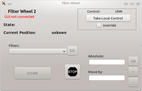
VisAO camera to exist peacefully as both a subsystem of the LBT AO Supervisor architecture, and as an independently controlled science camera. It is designed so that in all cases science has precedence, and user action cannot accidentally interfere with an observation in progress.Control mode is managed in the Engineering GUIs with a common interface, shown in the below figure. When possible, you can request LOCAL control by pressing the button. When necessary you can request an override first by checking the box.
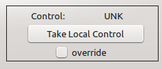
The Control Mode block common to all Engineering GUIs.
- Note
- If you ever find that a button is grayed out, or a GUI seems unresponsive, the first thing you should check is control mode.
This is the user's guide to the main
VisAO camera control GUI, VisAOEngGUI. All
VisAO GUIs are hosted on the main
VisAO computer, visaosup.lco.cl. This GUI can normally be launched from the
VisAO operator's workstation by double-clicking on the "VisAO S/W" icon on the desktop. Alternatively, one can ssh directly into visaosup and launch the GUI with:
ssh -Y v.vis
./VisAOEngGUI &
where v.vis is an alias in the host file for 192.168.3.5, which is the address of visaosup on the VisAO VLAN. This assumes that you are operating as the aosup user on the VisAO workstation, and that password-less login has been established between the workstation and visaosup.
Main Window
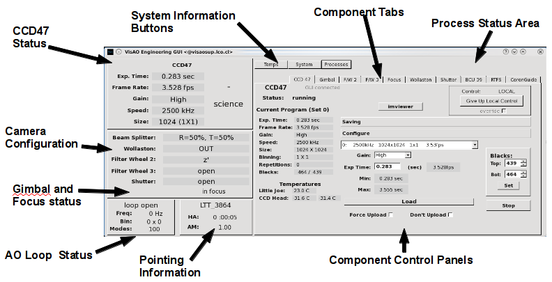
The main control window of the VisAO camera
This is the user's guide to the CCD47 Control GUI.To control the CCD47 select the CCD47 tab. On the left of the tab the current program set is indicated, and below that the current operating parameters of the CCD47 are displayed. Below this are the current Little Joe (case) temperature, and the two head temperatures.A button to launch the image viewer is provided in the top middle of the tab.Within the CCD47 tab are two tabs which collect different functions. The first is the Configure tab.
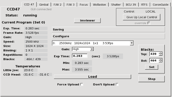
The CCD47 Control tab with the Configure tab selected.
The Configure tab is where the user changes the operating parameters of the CCD47. The first drop down box contains an entry for each available program, organized into program sets. A program consists of pixel speed, window, and binning. The list also shows the frame rate. When a program is selected, the
Min and
Max exposures times are updated.The second drop down box allows the user to select gains, with four possible settings: HIGH (most sensitive), Med. HIGH, Med. LOW, LOW (least sensitive). HIGH gain typically only has a depth of ~8000 electrons, while the LOW gain setting uses the full well depth of the CCD 47, approximately 100,000 electrons. Refer to the CCD 47 calibrations section for detailed information about the gains and associated readout noises.The user specifies the exposure time by typing a number in seconds into the
Exp Time box. Typing 0 will set the minimum exposure time. When the desired parameters are selected, pressing
Load will re-program the camera with those new settings. Both gain and exposure time can be changed by themselves, meaning that you do not need to specify the other parameters before pressing load.Selecting a new program within the same program set takes only about 1 second. Selecting a program in a different program set will take 30 to 45 seconds because the new set of programs needs to be sent to the CCD. A progress bar is shown during this process.The two check boxes below the Load button do not normally need to be used. If
Force Upload is checked, the selected program set will be uploaded, whether it is needed or not. If
Don't Upload is checked, then no parameters are sent to the CCD47, rather just the software state is updated.
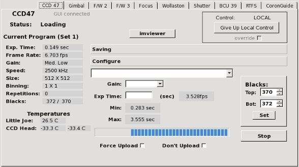
The CCD47 Control tab while loading a new program set.
There are two channels on the CCD47, each with its own black level. Default black levels are loaded with each program change. They can be changed using the GUI. New levels are not sent to the little joe until the Set button is pressed.Finally, the Configure tab allows the user to Start or Stop the CCD 47 (the button changes functions). It is normally running.
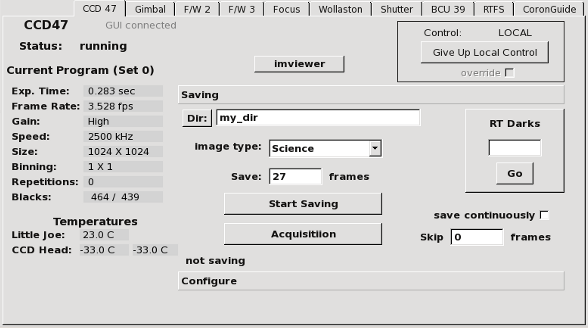
The CCD47 Control GUI with the Saving tab selected.
The
Saving tab controls various ways of saving data. The user can specify the directory in which to save, which is always relative to the main data directory. Simply typing a directory name in the box will set a new directory, which will be active when the saving starts. The
Dir button will also launch a file selection window.The
Image type drop down meanu allows you to set the image type, which is written to the VIMTYPE fits keyword. Note: choosing Dark automatically closes the shutter.The number of frames to be saved is typed into the
Save box. The
save continuously box can be checked if you instead desire to start saving until your press stop. Frames can also be skipped if desired, which can be useful if taking a very long timeseries to track a system parameter for engineering purposes (e.g. temperatures or bias levels).Once
Start Saving is pressed, the status of saving is updated both below this button, and in the main status board panel. The button then becomes the
Stop Saving button, and pressing it will stop saving.The
RT Darks area allows you to take a dark which can then be used on the image displayer, but is not written to disk. Enter the number of frames to average, and then press
Go. The new dark will be used immediately when it is complete.
This is the user's guide to the
VisAO imviewer, the real time image viewer.
Main Window
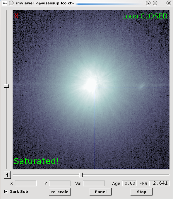
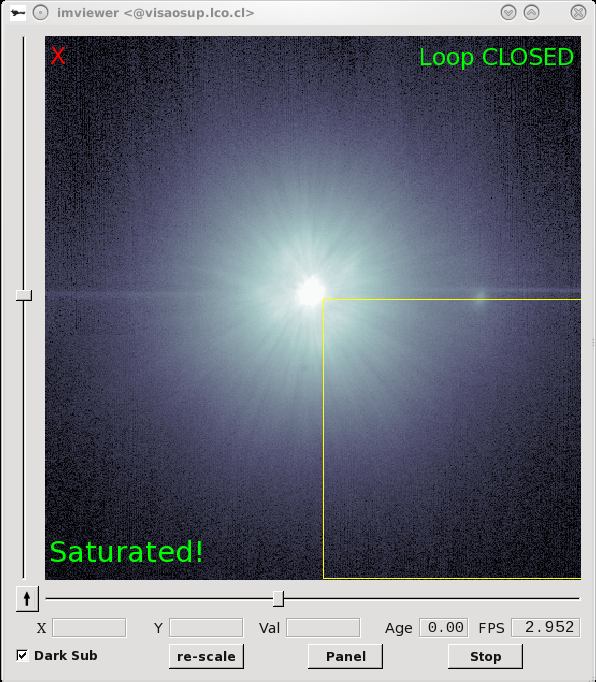
The main window
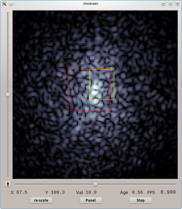
The main window of imviewer. Visible are the imviewer_statsbox and Color Box
Control over several options is provided via the main window. The zoom level can be changed using the mouse wheel (note that this works opposite to the ds9 convention,
VisAO flies like an airplane). The view center can be changed by center-clicking on the desired location, or using the sliders. The arrow button in the lower left corner hides/shows the bottom row of gages and buttons. Most of these functions have keyboard shortcuts, listed below.
Along the bottom the x-y coordinate of the mouse pointer, and the pixel value at that point are displayed. The age of the current image (how long it has been displayed) and the average frame rate are also shown.
The re-scale button adjusts the color bar scale using the current image. The Panel button launches the control panel, and the Stop button freezes real-time updating of the display.
Control Panel
The control panel provides detailed control over various imviewer settings. It can be launched by pressing the "Panel" button on the main window, or by pressing p in the main window. The following sections and figures describe the various functions of the control panel.
The View Tab
The View tab provides control over the zoom level, the center of view, and also provides numerical details and a finer view based on the mouse cursor position.
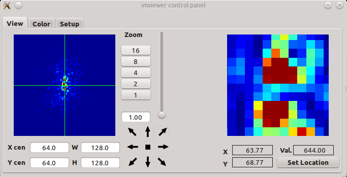
The view tab of the control panel. From here one can control the zoom and ceter of view, and use the mouse cursor for a finer view.
Zoom can be changed by pressing one of the zoom buttons, with the slider, typing in the box below the buttons, by changing the Width or Height using W and H fields, or by pressing a number from 1-9. The center of view can be changed using the X and Y fields, or by using the arrow buttons. The current zoom and center is indicated by the cross and box in the zoom view at left. At right is the mouse pointer view which shows the region under the mouse cursor at an additional zoom. Under the view the coordinate and pixel value of the mouse cursor are shown. The pointer view can be fixed in a certain location by first pressing the Set Location button, then left clicking in the main window at the desired location."
The Color Tab
The Color tab provides control over display colors, including the scale, bias, contrast, and the color map.
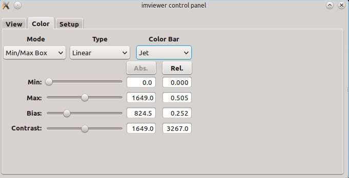
The Color tab of the control panel.
The Mode drop-down box gives the following choices:
-
Min/Max Global The scale minimum and maximum are set based on the whole image
-
Min/Max View The scale minimum and maximum are set based on the current view (not implemented)
-
Min/Max Box The scale minimum and maximum are set based on the color box
-
User The scale minimum and maximum are set by the user
The user can change the scale min and max by right clicking and dragging (as in ds9), or by adjusting the appropriate slider or directly entering the desired values in the relevant boxes.
The scale type dictates how the color map is assigned to image values. The Type drop-down box gives the following choices:
-
Linear
-
Log
-
Power
-
Square Root
-
Squared
The choice of color bar dictates the colors of the image display. The Color Bar drop-down box gives the following choices:
-
Grey
-
Jet
-
Hot
-
Bone
-
Red
-
Green
-
Blue
The Setup Tab
The Setup Tab provides control over several options.
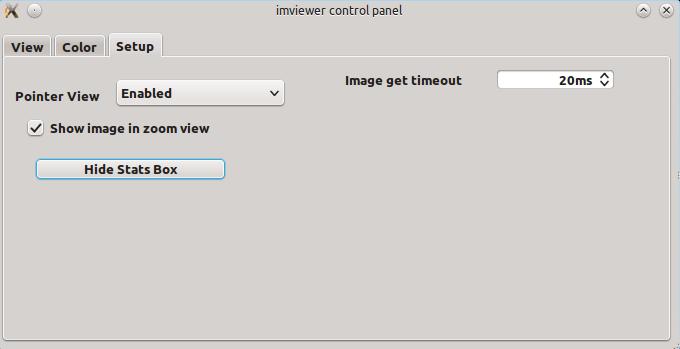
The Setup Tab of the control panel.
The behavior of the pointer view (visible in the View Tab) can be changed to trade-off between responsiveness and speed. The pointer view drop-down offers the following choices:
-
Enabled will cause the pointer view to always display the data under the mouse cursor
-
On Mouse Press will cause the pointer view to only display data when the mouse is left clicked. This should be selected if high frame rates are desired, and is the default
-
Disabled causes the pointer view to never display data
The check box controls whether the zoom view is updated with every image. The default is unchecked, and should be the choice when performance is important.
The stats box button controls whether the red statistics box is visible and the attendant stats window is shown.
The image get timeout controls the length of time that imviewer pauses before checking for a new image in the shared memory circular buffer. This should normally be short (20 ms is the default) to provide responsiveness in high frame rates.
Statistics Box
The statistics box is a tool for calculating and displaying some statistics about a region of the image in real time. These stats are calculated in a separate thread, and so update as soon as they are calculated, but may not be perfectly synchronized with the display. This is especially true for if the stats box is large. The stats are displayed numerically in the Stats Panel, and some of them can be plotted as a time series.
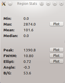
The Stats Panel shows several statistical quantities. For select quantities, a real time plot can be launched showing a short history.
The Stats Panel currently shows the latest value of the minimum, maximum, mean, and median. A 2D Gaussian is also continually fit to the data, and the resultant best fit peak value, FWHM, ellipticity, angle of the major axis, and the background level are displayed.
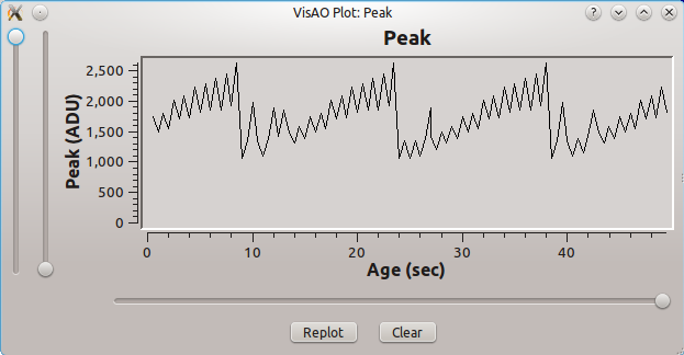
The Stats Plot shows a time series of the selected quantity. The sliders allow adjusting the associated axis scale.
The stats plot shows a real-time updating time series of the selected quantity. Along the y-axis, the left slider adjusts the y-axis maximum, and the right slider adjusts the minimum. Along the x-axis the slider adjusts the time maximum. The time minimum is always zero.
Color Bar
The selected color bar defines what colors are mapped to the intensity levels in the image data. In the future the available color bars will be listed here, with illustrations.
Keyboard Shortcuts
The following keystrokes are shortcuts for actions in imviewer. Note that they are case sensitive.
-
p launches the Control Panel.
-
r re-stretches the Color Bar
-
b shows or hides the color box
-
s shows or hides the Statistics Box
-
x starts or stops the real time updating
-
n hides or shows the north arrow.
-
t hides or shows the target crosshairs
-
c centers the display
-
1-9 changes the zoom setting
This is the user's guide to the Focus Stage GUI.In the top top half of the GUI you can see the current power status of the controller and the current position. The STOP button is always visible regardless of which tab is selected. Pressing the STOP button will immediately stop the stage.As usual, you must have LOCAL control of the stage to make changes from this GUI.

The Focus Stage Control GUI with the Move To tab selected.
The Move To tab is normally selected by default. The stage can be moved from this tab in three different ways.To move to an absolute position, type the desired position in microns into the box labeled Absolute: and press go.To move to a new position relative to the current position, type the size of the move (absolute value), and press the + or - button to move in the desired direction.To move the stage to a preset position (based on filter selections), select the desired preset from the dropdown menu and press go.

The Focus Stage Control GUI with the Advanced tab selected.
The Advanced tab provides some auxiliary controls. The Enable/Disable button allows you to change the status of the motor current outputs from the controller. This so far appears to be unnecessary at any time. The Check blocks indicate the status of the limit switches (the Home Switch is no longer installed and it is ignored by the Focus software). The Home buttons cause the stage to home to the corresponding hall sensor limit switch. Homing is not necessary in normal operations, and is usually completely useless due to the high degree of uncertainty in the hall sensor activation position. The Home button itself has no effect due to the lack of an installed home switch.
This is the user's guide for scripting operations of the
VisAO camera.
VisAO camera scripting is provided in the "visao" python module, which controls the various
VisAO devices.
Invoking VisAO Script
Before running a script, the visao python module must be initialized. As user aosup on the visaosup computer, simply open a terminal and type python:
[aosup@visaosup ~]$ python
Python 2.4.3 (#1, Jan 9 2013, 06:47:03)
[GCC 4.1.2 20080704 (Red Hat 4.1.2-54)] on linux2
Type "help", "copyright", "credits" or "license" for more information.
VisAO script control initialized
>>>
This automatically initializes the visao module.
Taking Science Data
The highest level script for taking science data is the "observation" script. It performs a sequence of observations a set number of times. In this script, an observation is a python tuple with the following structure:
obs= (fw2Name, fw3Name, PixRate, Window, Gain, ExpTime, TotExp, MasterDarks, DarkInt, nDarks, subdir)
The entries have the following definitions:
- fw2Name = a string, with possible values 'open', "r'", "i'", "z'", or "Ys"
- fw3Name = a string, with possible values "small spot", "SDI H alpha", "SDI [S II]", "open", "ND 3.22", "large spot"
- PixRate = integer pixel rate, with possible values 2500, 250, or 80
- Window = window size, with possible values (depending on PixRate) of 1025, 512, 256, 64, 32
- Gain = a string, with possible values of 'H', 'MH', 'ML', or 'L'
- ExpTime = exposure time of each frame in seconds. Set to 0 for minimum exposure time.
- TotExp = the desired total open-shutter exposure time of the observation
- MasterDarks = the number of darks to take at the beginning of the observation
- DarkInt = the time interval, in seconds, between taking darks, 0 means no subsequent darks
- nDarks = the number of darks to take at each interval
- subdir = the subdirectory in which to put these files
The observation script is invoked as
>>> vis.observation(observations, repeats, subdir="", appendts=1)
Where:
- observations = an observation or a tuple of observations
- repeats = the number of times to repeat. If <=0, then the observations are repeated until stopped
- subdir = the top level subdirectory in which to place each observation
- appendts = if 1, then a visao time stamp is appended to subdir
Here's an example:
>>> obs1 = ("z'", "open", 2500,1024, 'H', 0, 30,5, 15,2, 'zp_unsats')
>>> obs2 = ("r'", "ND 3.22", 2500,1024, 'ML', 1, 30,5, 15,3, 'rp_sats')
>>> vis.observation((obs1, obs2),0,"obs_example",0)
Another useful script is the science script. This manages taking a set of science exposures, up to a total exposure time, while taking shutter-closed darks at specified intervals. Note that this is actually called by the observation script. Once the visao module is initialized, the syntax to call the science script is:
>>>vis.science(totexp, exptime, masterdarks, darkint, ndark, "my_directory_name", appendts=1)
where:
- totexp = the total exposure time, in seconds
- exptime = the exposure time, in seconds, of individual frames
- masterdarks = the number of initial darks to take
- darkint = the interval at which to take subsequent darks
- ndark = the number of darks to take after each interval
- "my_directory_name" = the name of the directory where you would like this data to be saved
- appendts = if 1 (the default), a time stamp is appended to the directory name every time the script is run. If 0 then the same directory is used.
You can see the full documentation of the science script here.
The Dither Script
Another useful, similar, script is the dither photometry script. This cycles through the list of filters, including setting the focus position, and executes a dither pattern with the VisAO gimbal. The list of filters can be set with the sdssFilters() function, and a 5 point dither pattern can be set using xDither() and yDither() as the arguments for dx and dy.
>>>vis.dither_phot(filters,nims, ndarks, dx, dy, "my_directory_name", appendts=1)
where:
- filters = list of filters to cycle through
- nims = the number of science images to take in each dither position per filter
- ndarks = the number of initial darks to take
- dx = gimbal x offsets from initial position, in mm
- dy = gimbal y offsets from initial position, in mm
- "my_directory_name" = optional subdirectory. if not specified, then dither_[timestamp] will be used
- appendts = if 1 (the default), a time stamp is appended to the directory name every time the script is run. If 0 then the same directory is used.
For entering the filters and dx, dy parameters see sdssFilters, xDither, yDither.
Getting Help
You can see everything in the VisAO python module here. To view the contents of the visao module from within python, you can use the dir() command:
Which will print
['CCD47Ctrl', 'FilterWheel', 'FilterWheel2', 'FilterWheel3', 'FocusCtrl', 'Shutter', 'VisAOFifoDev',
'__builtins__', '__doc__', '__file__', '__name__', '__package__', 'get_visao_filename', 'math',
'os', 'select', 'time']
The documentation for the module can be viewed with:
You can also get class specific help with either
or
For more a more detailed introduction to python see the python documentation online.
Other Examples
Several examples using VisAOScript are contained in the FocusOps.py script. These include the script used to calibrate the focus stage step ratio, and scripts to perform a focus measurement and to focus the camera in a sequence of filters.
"""
FocusOps
The FocusOps python module contains several scripts related to the focus stage..
"""
import VisAOScript
import numpy
import time
"""
Script to calibrate the focus stage step-ratio. Requires manual input of a micrometer measurement, in mm.
Moves to the front or back of the travel range, whichever is closer when invoked.
"""
foc = VisAOScript.FocusCtrl()
foc.take_control()
if p == 0:
d = foc.get_pos()
if d > 5500.:
poss = 11500. - array(range(9))*2500.
else:
poss = -9500. + array(range(9))*2500.
else:
poss = p
cal_pos = list()
meas_pos = list()
for i in range(len(poss)):
print "************************"
print "Moving to %f microns." % poss[i]
resp = foc.pos(poss[i])
if(resp != 1):
break
resp = foc.wait_move()
if(resp != 1):
break
pos = foc.get_pos()
print "At %f microns." % pos
meas = float(raw_input("Enter measurement (in mm): "))
print "%f %f" % (pos, meas)
cal_pos.append(pos)
meas_pos.append(meas)
x = array(cal_pos)
y = array(meas_pos)*1000.
A = numpy.vstack([x, ones(len(x))]).T
m,b = numpy.linalg.lstsq(A,y)[0]
yfit = m*x + b
resid = yfit-y
print "\n\nCalibration Complete\n\n"
print "y = %f + %fx" % (b, m)
print
"\nStd dev of residuals: %f microns\n" % numpy.
std(resid)
print "Data:\nPosition\tMeasured\tResidual"
for i in range(len(cal_pos)):
print "%f\t%f\t%f" %(cal_pos[i], meas_pos[i], resid[i])
foc.giveup_control()
def
focus(start, end, stepsz, ims=5, settle_delay = 1.):
"""
Peform a focus measurement.
Moves from position start to end, in steps of size stepsz.
At each position, the script pauses for settle_delay to allow vibrations to dissipate, and then take ims images.
Images are saved in a sub-directory with the start time (standard VisAO filename) in the name.
"""
foc = VisAOScript.FocusCtrl()
foc.take_control()
ccd = VisAOScript.CCD47Ctrl()
ccd.take_control()
dist = abs( end - start)
if abs(stepsz) < 5.:
print "Stepsize too small."
return
if end < start:
if stepsz > 0:
stepsz = stepsz * -1.
else:
if stepsz < 0:
stepsz = stepsz * -1.
if ims <= 0:
print "Number of images must be > 0."
return
print "************************"
print "Moving to %f microns." % start
resp = foc.pos(start)
if(resp != 1):
print "Focus motor error. "
return
resp = foc.wait_move()
if(resp != 1):
print "Focus motor error. "
return
pos = foc.get_pos()
print "At %f microns.\n\nBeginning focus curve acquisition . . ." % pos
nextpos = pos
ccd.subdir(sd)
while abs(nextpos - start) < (dist + .1*abs(stepsz)):
print "************************"
print "Moving to %f microns . . ." % nextpos
resp = foc.pos(nextpos)
if(resp != 1):
print "Focus motor error."
return
resp = foc.wait_move()
if(resp != 1):
print "Focus motor error."
return
pos = foc.get_pos()
print "Move complete. Settling for %f seconds . . ." % settle_delay
time.sleep(settle_delay)
print "Saving %i images at %f microns." % (ims, pos)
resp = ccd.save(ims)
if(resp != 0):
print "CCD47 error. "
return
resp = ccd.wait_save()
if(resp != 1):
print "CCD47 error. "
return
print "Saving complete."
nextpos = pos + stepsz
print "\n\nFocus Curve acquistion complete.\n\n"
ccd.subdir(".")
foc.giveup_control()
ccd.giveup_control()
def
filter2_focus(filters, homefirst, start, end, stepsz, ims=5, settle_delay = 1.):
"""
Peform a focus measurement, in each of a sequence of filter wheel 2 positions.
The filters are specified as a python list, i.e. ["SDSS r'", "SDSS i'", "SDSS z'"]
If homefirst is true, the wheel is homed before beginning.
In each filter, the focus script is executed.
"""
fw2 = VisAOScript.FilterWheel2()
fw2.take_control()
if homefirst:
print "Homing FilterWheel2. . ."
resp = fw2.home()
resp = fw2.wait_home()
time.sleep(5)
print "Homing complete."
for i in range(len(filters)):
print "Changing filter to %s . . ." % filters[i]
resp = fw2.set_filter(filters[i])
resp = fw2.wait_move()
time.sleep(2)
filt = fw2.get_filter()
print "In filter %s . . ." % filt
if filt!= filters[i]:
print "Filter not correct."
return
focus(start, end, stepsz, ims, settle_delay)
fw2.giveup_control()


 1.8.9.1