|
The VisAO Camera
|


|
|
The VisAO Camera
|
|
Guide to reducing VisAO data. More...
Data contained in the FITS headers of VisAO data are read from the end of the readout of the camera, that is from the end of the observation plus the readout time. Due to polling times and update latencies, these data could be even several seconds older. Note that the readout time of the camera does not depend on exposure time, and the longest readout time of the camera is 6.7 seconds, and will usually be much shorter.
The FITS keywords most useful for data reduction are:
The complete VisAO FITS header can be viewed here: Complete Fits Header.
The VIMTYPE keyword can have the values ACQUISITON, SCIENCE, SKY, DARK, or FLAT. During a typical science observation, some combination of ACQUISITION, SCIENCE, SKY and/or DARK images will be contained in the same subdirectory. The VIMTYPE keyword can be used to sort images.
The bias level of the little joe 47 depends on temperature of the CCD Electronics box (mounted on the NAS). This box is glycol cooled to ambient temperature, and so will change with time. The normal method for compensating for CCD bias drift is to use an overscan region of the chip as an estimation of bias. This capability exists for the VisAO CCD47, but has not been implemented yet, mainly due to its impact on speed, the fact that it only works on full-frame modes, and Jared just never got around to it. VisAO does not have the ability to take true zero-length bias frames, rather we just take full-length shutter-closed dark images to track bias level.
Typically, a short sequence of shutter-closed darks is taken periodically throughout a science data set. A master dark is taken at the beginning and/or end, and the interim darks are used to scale the master dark with time. Note that the CCD 47 has two amplifiers with slightly different characteristics, so the two halves of the chip should probably be treated independently in dark subtraction over long data sets.
The ROTOFF keyword, which comes from the TCS, contains the nominal value by which to derotate an image to get North-up East-left (NUPEL). For a VisAO image there is an additional rotation of 90 degrees due to the overall mounting orientation, and a small offset from there which is calibrated run to run to account for the as-built and as-mounted orientation. To get a true NUPEL image (whether rotator tracking or rotator off) use:
![\[ DEROT_{VisAO} = ROTOFF + 90.0 + NORTH_{VisAO} \]](form_0.png)
where  is the amount, in degrees, to rotate counter-clockwise. The exact value of
  will be provided as part of each run's calibrations (see below for our nominal value). Note that PARANG contains the TCS value of the parallactic angle at the end of the observation, and ROTANG contains the value of the rotator encoder angle, and
  .
.
During each run we will perform astrometric calibrations of the VisAO camera. As of 2014 May 6 we have not yet analyzed this data for 2014A. A quicklook performed during the run showed no major change from our previous values of:
= -0.59 +/- 0.3 degrees
 = 7.9 +/- 0.02 mas/pix
See Males et al 2014 for the details of these numbers.
The CCD 47 readout rates and gains are changed often to optimize sensitivity and control saturation. A common situation is to have frames in one setting where the primary star is saturated, and a set of unsaturated frames in a faster frame rate and/or lower gain setting. Each camera program, which consists of pixel rate, window size, and binning, has four discrete gain settings. The HIGH setting is the most sensitive, meaning lowest read noise and least digitization noise. The tradeoff is with the depth of the camera. The digital depth is always 16383 ADU, and in the HIGH gain setting this translates to only about 8000 electrons. The LOW gain setting always has much higer digitization noise, but give access to the full ~100,000 electron well depth of the CCD 47.
The following table gives the gains and readout noise (RON) for the most commonly used modes. Values for additional modes are available upon request.
| Mode | Gain Setting | Gain (e-/ADU) | RON |
| 2500 kHz 1024x124 bin 1x1 | HIGH | 0.53 | 9.7 |
| MED HIGH | 1.53 | 9.55 | |
| MED LOW | 3.58 | 10.74 | |
| LOW | 13.23 | 15.47 | |
| 2500 kHz 64x64 bin 1x1 | HIGH | 0.54 | 9.62 |
| MED HIGH | 1.93 | 9.58 | |
| MED LOW | 3.58 | 10.86 | |
| LOW | 13.14 | 15.49 | |
| 250 kHz 1024x124 bin 1x1 | HIGH | 0.47 | 4.52 |
| MED HIGH | 1.77 | 4.67 | |
| MED LOW | 3.34 | 5.28 | |
| LOW | 12.3 | 11.11 | |
| 250 kHz 512x512 bin 1x1 | HIGH | 0.48 | 3.84 |
| MED HIGH | 1.77 | 4.25 | |
| MED LOW | 3.32 | 4.88 | |
| LOW | 12.36 | 10.52 |
It is useful to convert from ADU to electrons per second when comparing images taken with different camera settings. To convert we calculate the scaling factor (SF) to multiply each pixel by. The formula is:
![\[ SF = \frac{GAIN}{EXPTIME}10^{ND} \]](form_5.png)
Where:
SF = scale factor which converts ADU to electrons/second
GAIN = the gain factor, in electrons/ADU. This depends on the gain setting (LOW, MLOW, MHIGH, HIGH) which is given in the fits header as V47GAIN, and the pixel rate which is V47PIXRT, and very weakly on the window size and binning. See the above table for the measured gains.
EXPTIME = the exposure time of the image, in VisAO fits headers it is given by the standard EXPTIME keyword.
ND = value of the neutral density filter if used, 0 otherwise.
Morning sky flats were found to be much better than evening sky flats. The direction that sunlight enters the dome in the evening causes significant glinting which does not appear to be as bad in the morning. Even in the morning, the illumination pattern is such that the resultant flat is only useful for high spatial frequency response (i.e. pixel to pixel), and some glinting is still visible with a sufficiently large smoothing kernel.
These flats were taken on the morning of 2014 Apr 18 UT, in the 50/50 beamsplitter and the z' filter. Exposure time was adjusted as the sky brightened to avoid saturation.
The following steps were taken to form the flat:
The choice of smoothing width affects the quality of the flat under the dust spots, which are of order 20 pixels wide, and it affects the rejection of mid-spatial frequency glints. By comparing a flat with an 11 and a flat with a 41 pixel smoothing width, we found that the major glint (which becomes visible in the 41 pixel flat) only raises the apparent response by ~0.2%. In contrast, the 11 pixel flat overstates the response under large dust spots by up to 1%. We recommend using the 41 pixel flat, but several choices (11,21,31, 41) are provided. A simple ratio of these images will allow you to analyze the tradeoffs.
Note that the ~10 pixels at the edge of the flats should not be used, as smoothing is suspect there.
Download: VisAO Flat with 11 pixel smoothing width
Download: VisAO Flat with 21 pixel smoothing width
Download: VisAO Flat with 31 pixel smoothing width
Download: VisAO Flat with 41 pixel smoothing width [RECOMMENDED]
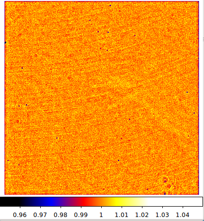
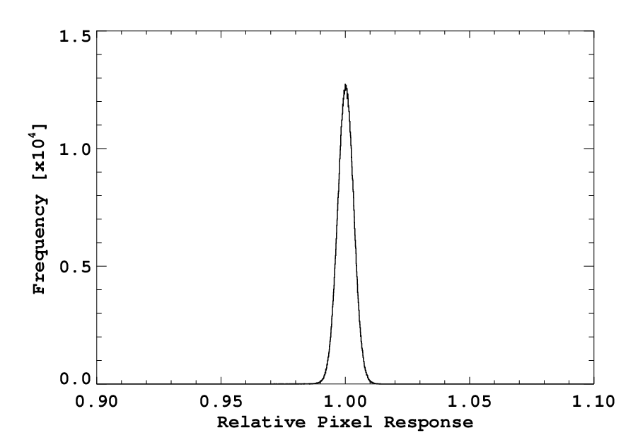
The VisAO camera pixel response is flat to better than 1%, with the exceptions of dust spots. Some statistics of the 41 pixel flat are given below. For these we excluded 10 pixels at the edge of the array where the smoothing is less effective.
mean response: 1.00011
median response: 1.00023
std. dev response: 0.00324769
min response: 0.935925
max response: 1.05748
-----------------—
more than 1% deviation
No. > 1.01 1397
No. < 0.99 1645
-----------------—
more than 2% deviation
No. > 1.02 14
No. < 0.98 201
-----------------—
more than 3% deviation
No. > 1.03 2
No. < 0.97 46
-----------------—
more than 4% deviation
No. > 1.04 1
No. < 0.96 8
-----------------—
more than 5% deviation
No. > 1.05 1
No. < 0.95 1
.
The ND was calibrated during 2014A on HD 84687 a V~7 F3V star. The following table gives the results.
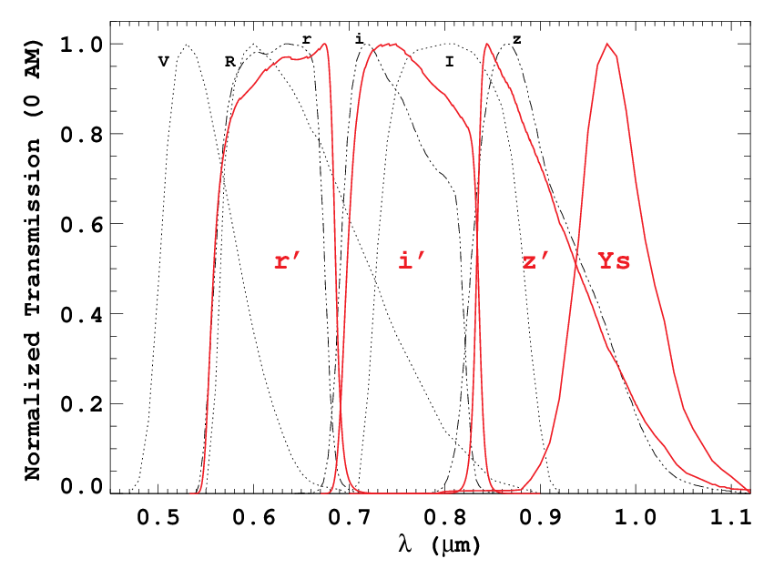
| Filter | Attenuation | ND |
| r' | 7763.6 +/- 433.5 (5.5%) | 3.89 |
| i' | 1452.9 +/- 37.8 (2.6%) | 3.16 |
| z' | 491.1 +/- 16.1 (3.2%) | 2.69 |
| Ys | 276.6 +/- 8.7 (3.1%) | 2.44 |
Full details of the calibration analysis are available in this document.
Throughput measurements for 2014A are in progress . . .
The astrometric calibration of VisAO for 2014A is ongoing . . .
 1.8.9.1