The SAO phasing prototype visits MagAO

“Without phasing, there’s no real reason to build the GMT.”
-Andrew Szentgyorgyi

The biggest optical/infrared telescope in world will be the Giant Magellan Telescope, which will be built on a nearby mountain peak within sight of the Clay and Baade telescopes at Las Campanas.  The telescope will have 7 primary mirror segments and 7 adaptive secondary mirrors, similar to the Magellan AO system.

The 25 meter diameter Giant Magellan Telescope
The 25.5 meter diameter Giant Magellan Telescope
Photograph of the GMT site from the Magellan footpath.

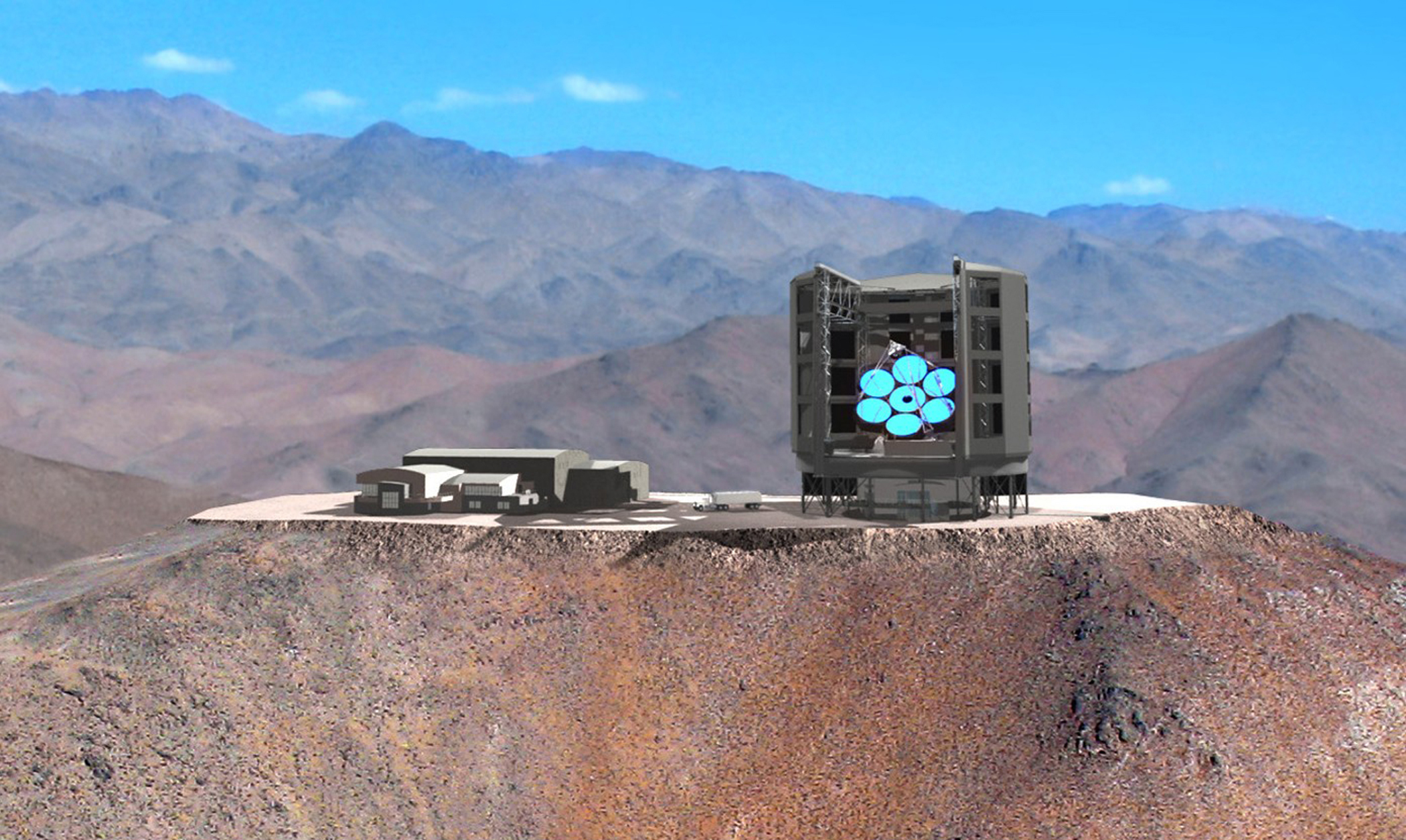
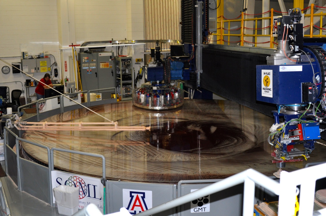
If we could build any optic we wanted for the primary of the GMT, we would probably build a monolithic 30 meter diameter (or larger) mirror made of a single piece of glass, with a thin face sheet and a honeycomb lightweight structure on back.  However, at the moment, the largest mirrors in the world are built in the Steward Observatory Mirror lab under the bleachers of the football stadium at the University of Arizona and are limited to a diameter of 8.4 meters.  Depending on who you ask, this 8.4 meter limit comes from either the distance between the columns underneath the stadium bleachers, or the size of an underpass on the highway leading from Tucson.

An 8.4 meter mirror being polished in the Steward Observatory mirror lab underneath the football stadium bleachers.  Making mirrors larger than this will require a larger football stadium.
An 8.4 meter mirror being polished in the Steward Observatory mirror lab underneath the football stadium bleachers. Making mirrors larger than this will require a larger football stadium.

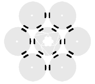
Because of this limit, the GMT is designed to take 7 of the largest mirrors that can be made and combine them to form one giant 25.5 meter primary.  For this to be possible, the seven 8.4 meter segments must be “phased” to a fraction of a wavelength.  That is to say, they must be aligned to each other so that they act as if they are one large continuous mirror.

To achieve the phasing of the GMT segments using off-axis natural guide stars, SAO and our collaborators at GMTO and Flat Wavefronts have designed a sensor that creates dispersed interference fringes using subapertures spanning the 12 segment boundaries.  Phase shifts across the segment boundaries manifest themselves as tilts in the fringes.

Segment boundary subapertures for the dispersed fringe phasing sensor.
Simulated fringes from one subaperture showing 0 piston phase difference (left) and 10 microns (right).

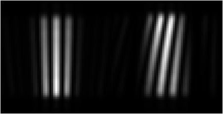
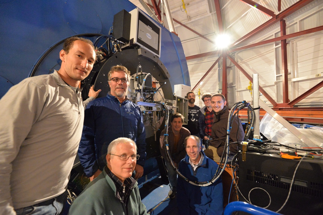
To test this sensor technology, SAO has built a phasing prototype that simulates 6 of the GMT segment boundaries working in conjunction with the Magellan AO system.  Our three nights at the end of the MagAO run turned out to be a success.

Six sets of fringes as seen by the SAO phasing prototype working in conjunction with the MagAO system.
The SAO phasing prototype team.  Clockwise from top left: Derek Kopon, Alan Conder, Ken McCracken, Jared Males, Laird Close, Dan Catropa, Brian McLeod, Bill Podgorski.
The SAO phasing prototype team. Clockwise from top left: Derek Kopon, Alan Conder, Ken McCracken, Jared Males, Laird Close, Dan Catropa, Brian McLeod, Bill Podgorski.

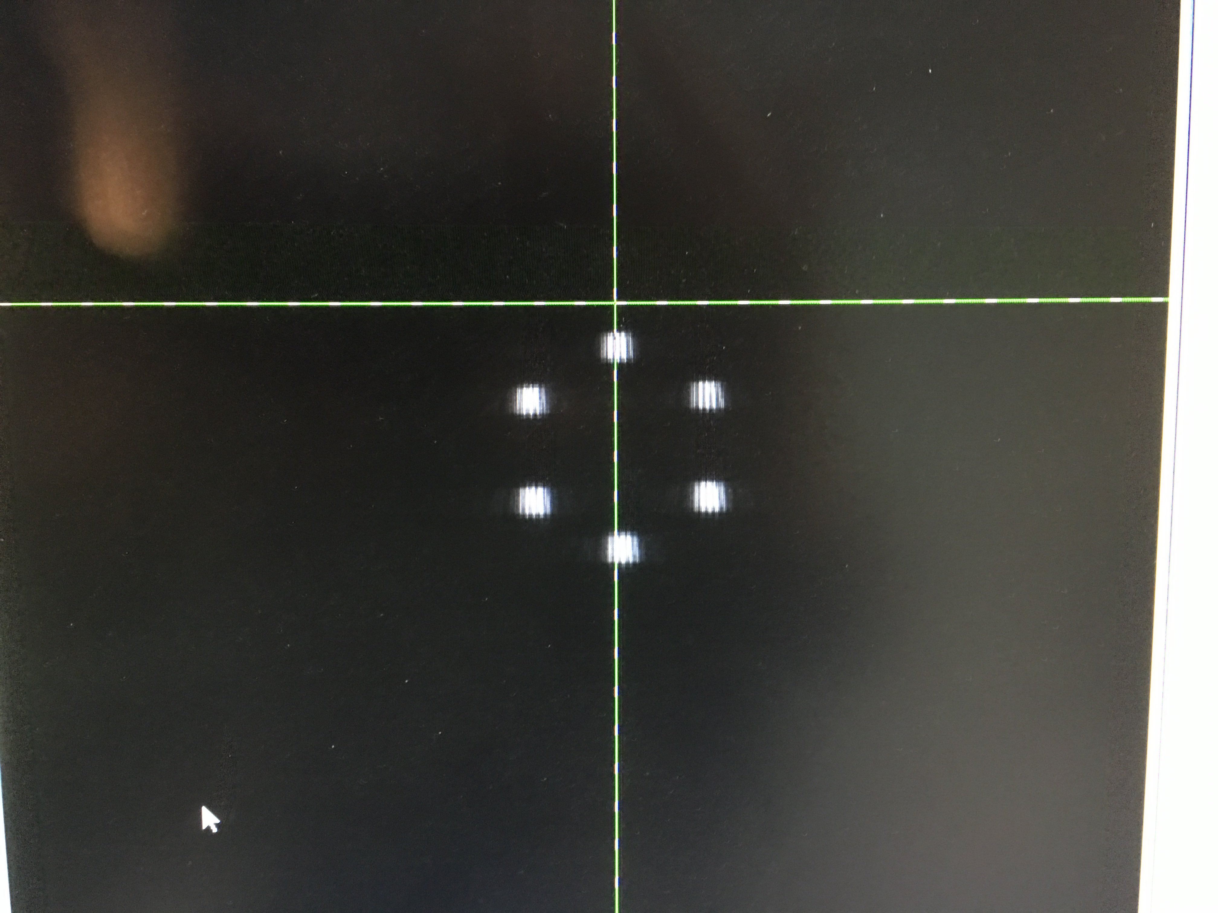
We obtained phasing data both on-axis and off-axis, with AO on and off, and at two different wavelength bands (I and J).  This data, and data that we gather during another run possibly in February, will inform the design of the GMT phasing sensor, scheduled for first light in the next decade.

Lastly, a “song of the run:”  Phazing, by Dirty South:

https://www.youtube.com/watch?v=031hzipvnTY

Alignment alignment alignment!

Okaayyy!!!  Allora.  The day began with some avocado slices, dos scrambled huevos, a bowl of oatmeal, two slices of cheese, two slices of breakfast cake, two glasses of fresh squeezed orange juice (delicious!), and a cafe con leche.  The food at LCO is very good and below are more pictures, for our respective mothers:

Some sort of meat and potato thing, asparagus, artichoke hearts, tomatoes, beets, and a glass of peach juice
Chicken with yellow rice, salad with beets, bowl of fresh fruit with strawberry ice cream, and a glass of peach juice. Eat your heart out LBT!
Meat empanada, marisco soup, bowl of fruit, and a glass of juice. Mmmm....

After breakfast, a view of the marine layer in the valley to the north awaited us at the telescope:

We arrived to an email from the crew from the previous night led by Laird and Povilas that told us they had managed to collimate the telescope to the seeing limit using the Shack-Hartmann wavefront sensor: a 0.55-0.6″ image on a >0.5″ night.  They then created a lookup/flexure table.

A 0.6 arcsec image taken with our wide-field guider probe after collimating the telescope
A guanaco by the side of the road

With that good news, the morning crew proceeded to the next step of mounting the Calibration Return Optic (CRO, now pronounced “crow”).  The CRO is a retroreflecting parabola/return flat optic that is aligned to the near ellipsoidal conjugate of the adaptive secondary.  Because Magellan’s Gregorian design uses a concave secondary, we can use the CRO to test the secondary off sky with a point source located at the Nasmyth focal plane.  We can also use the CRO to run the entire AO system closed loop with an artificial source during the day.  The CRO is in a small cup that mounts to a 5 axis remotely actuated piezo stage, which in turn mounts to its own truss structure.  This truss structure was assembled and aligned during the tower tests in Italy in order to locate the CRO at the ASM conjugate to a mm or so (hopefully better).  The truss is carefully passed through the secondary cage and bolted directly in front of the ASM.

Attempting to write warning labels in Spanish
Carefully installing the CRO to the magnetic kinematic interface on the truss
Checking the CRO alignment with the boresight gun laser. It's good!
A magnified image of the CRO looking through the cage at the secondary
Pato running some CRO cables along the structure
Jared and Pato high up in the scissor lift to run the CRO cables along the spider vanes.
Armando putting a fiducial on the primary-facing side of the CRO truss, along the optical axis
Armando setting up the crosshair fiducial at the Nasmyth focal plane. This fiducial allows us to align the optical axis of the secondary to the rotational axis of the Nasmyth rotator.
Armando, Marco, and Jared going through the alignment procedure
Looks pretty aligned to me!

Overhead at LCO today:

“Seven.” -Derek to Marco after counting the number of spoonfuls of sugar the PI added to his tea.

“I always lose count because he’s talking while he’s doing it.” -Armando, regarding the PI adding sugar to his tea.

“Derek, you seem a bit tired, perhaps you need some more sugar in your tea.”  -Marco

“I would like a siesta, a wonderful Spanish invention.” -Alfio

“It’s temporary, but it may become permanent.”  -Pato Jones.  Was he talking about something in particular or MagAO in general?

Some lovely pictures of the telescopes opening last night at dusk:

Baade on the left, Clay on the right

Into the Test Tower!

Today we raised our hexapod-mounted adaptive secondary mirror (ASM) into the Arcetri test tower in Florence, Italy.  The large tower will allow us to operate the secondary at the same focal length and optical conjugates as the Magellan telescope in Chile.  We’ll use this test setup to interferometrically test the performance of our ASM and to close the loop on our full AO system.

The Arcetri Test Tower
The concave ellipsoidal ASM with a retroreflector mounted at its short conjugate is raised into the tower.
A grad student magnified by the F/1.1 ASM
Armando Riccardi trapped inside the looking glass!
The Ring anyone?
The Ring anyone?

92% Strehl Sloan r’ Image

The below image is our 92% Strehl Sloan r’ band image with our triplet ADC and dichroic beamsplitter in the beam.  The slight elongation of the PSF and the asymetric contrast of the fringes are due to the “zenith spike” effect of the ADC.  This effect is predicted by our models and will not manifest itself on-sky when the atmosphere will counteract the residual chromatism of the ADC.

Spot diagram showing the broadband chromatic "zenith spike" effect of the ADC in the lab.